静态路由实验
post on 05 May 2019 about 6783words require 23min
CC BY 4.0 (除特别声明或转载文章外)
如果这些文字帮助到你,可以请我喝一杯咖啡~
实验题目
静态路由实验
实验目的
掌握静态路由的配置和使用方法。
实验命令
查看接口
1
2
3
#show interface
#show ip interface brief
#show ip interface f0/1
配置 IP 地址和子网掩码
1
2
(config)#interface serial 1/2                       !进行接口模式
(config-if)#ip address 192.168.1.11  255.255.255.0   !配置接口的IP地址和子网掩码
配置串口时钟和带宽
1
2
(config-if)#clock rate 64000               !配置时钟频率64000(在DCE上配置,DTE不用配置)
(config-if)#bandwidth 512                !配置端口的带宽速率为512KB
配置静态路由
1
(config)#ip route network net-mask next-hop  ! next-hop可以为转发的串行接口名或下一跳的IP地址
例:
1
2
ip route  192.168.3.0  255.255.255.0  192.168.2.2
ip route  192.168.3.0  255.255.255.0  S2/0
显示路由表
1
#show ip route
配置静态路由参数
1
2
3
(config)#ip route network net-mask next-hop  [distance]  [weight number]  [disable|enable]
!distance设置管理距离(默认为1),weight为权重。
! 将distance设置为一个大的值(例如,125。这大于OSPF的110)可以作为备份路由。
配置默认路由
1
(config)# ip route 0.0.0.0  0.0.0.0  next-hop
例:
1
ip route  0.0.0.0  0.0.0.0  192.168.2.1
配置交换机端口镜像
1
2
3
4
Switch(config)#monitor  session 1  source  interface  f0/15    ! 监控f0/15
Switch(config)#monitor  session 1  destination  interface  f0/5  ! 用f0/5监控
Switch(config)#show  monitor  session  1                	! 显示监控情况
Switch(config)#no  monitor  session  1                  	! 取消监控
实验说明
- 配置前先重启路由器
#reload - 参与 ping 的主机要删除校园网网关。
- 注意关闭 Windows 的防火墙
实验任务
由于实际上所用的接口名不一定是上面标明的,先用#show interface 查看接口名,并根据实际接线修改上图的接口和 IP 地址标记。 配置好 PC 机实验网网卡的 IP 地址、子网掩码和默认网关,按下面步骤依次进行配置和检测:
配置 Router1 和 Router2 的 IP 地址和子网掩码 (见上面「实验命令」)。
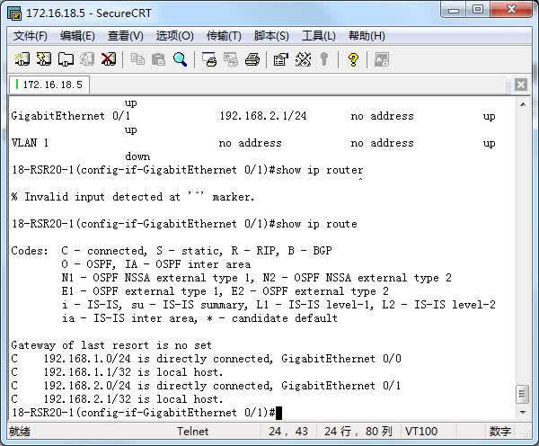
显示 Router1 的路由表并截屏
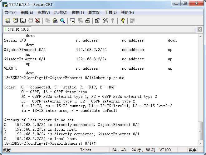
显示 Router2 的路由表并截屏
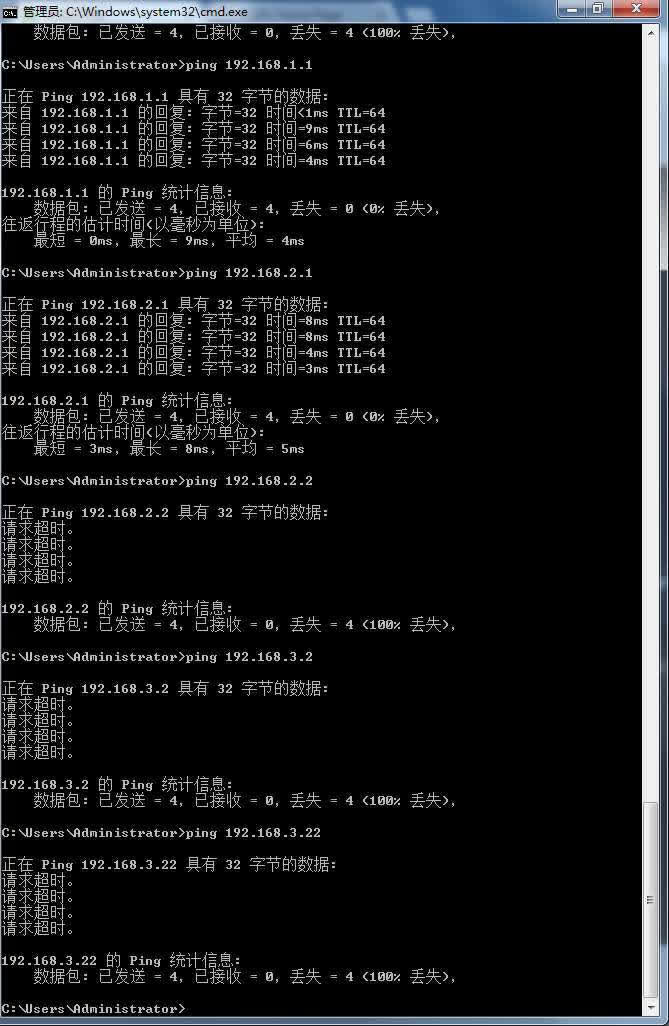
PC1 依次 ping 到 PC2 路经上的所有 IP 地址,并截屏
分析 Router1 路由表和 Router2 路由表的路由组成
第一行和第三行是此次实验新设的 IP 地址以及对应的连接端口。而第二和第四行则说明本路由器拥有的 IP 地址和对应的端口。
在 Router1 和 Router2 上配置静态路由(见上面命令或课件),要求 PC1 可以 ping 通 PC2。
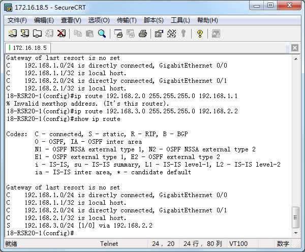
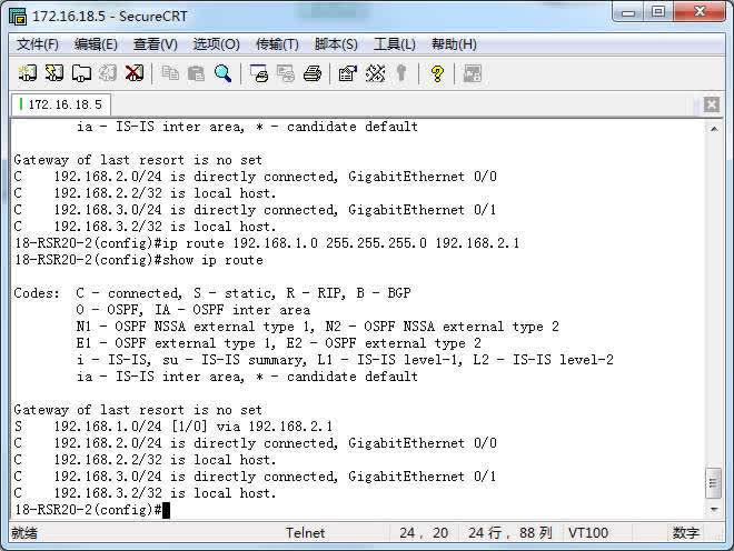
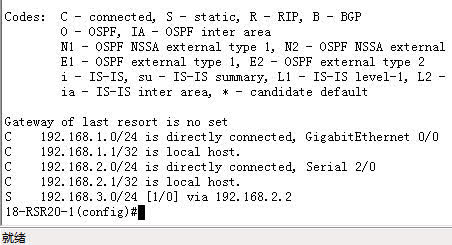
显示 Router1 的路由表并截屏
显示 Router2 的路由表并截屏
PC1 ping PC2 并截屏
分析 Router1 路由表和 Router2 路由表的路由组成
此时相比于(1),每一个路由器多了一行「S 192.168.X.X」,这是新配置的静态路由。路由器 1 的静态路由配置为网络号:192.168.3.0,端口为 192.168.2.2.路由器 2 的静态路由配置为网络号:192.168.1.0,端口为 192.168.2.1.
如果只在 Router1 上配置静态路由(删除 Router2 上配置的静态路由), PC1 和 PC2 都 ping 到对方路径上的 IP 地址,最远可以 ping 通哪个接口?为什么?
删除配置命令的方法是在原配置命令前加 no(和一个空格)。用上下键可以显示出历史命令。
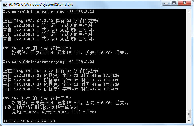
PC1 依次 ping 到 PC2 路经上的所有 IP 地址,并截屏
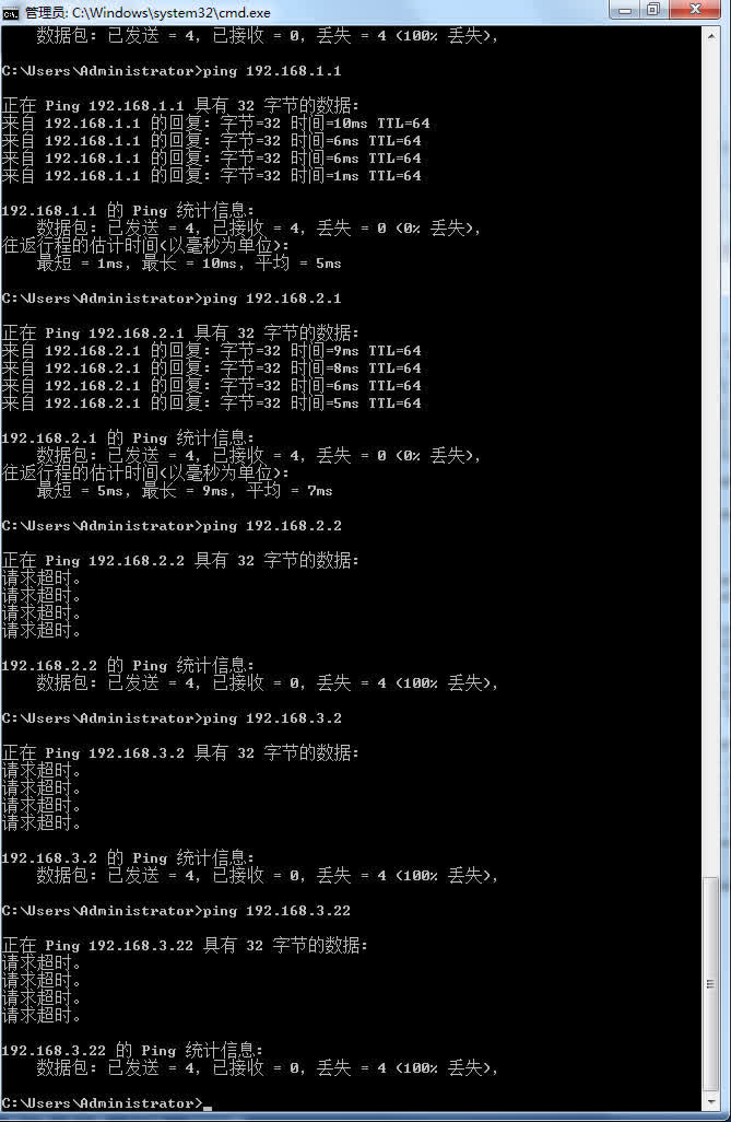
PC2 依次 ping 到 PC1 路经上的所有 IP 地址,并截屏

分析结果
此时的 PC2 由于路由器 1 的静态路由没有删除,所以可以有路由表找到前往 192.168.2.1 的路径,但由于路由器 2 的静态路由删除,所以并不能找到对应的路径前往 PC1.
PC1 可以到达路由器 1 的两端。由于路由器 2 的原因,不能 ping 通路由器 2 的两个端口以及 PC2.
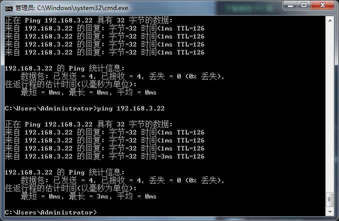
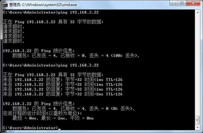
如果在路由器 Router1 和 Router2 只配置默认路由指向对方(要先删除原静态路由),PC1 是否可以 ping 通 PC2?为什么?写下分析。
PC1 ping PC2,并截屏
显示 Router1 的路由表并截屏
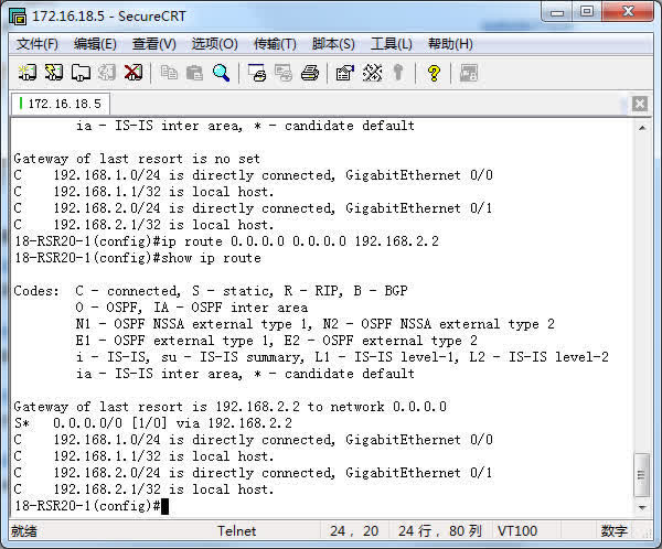
分析结果
由于在 router1 的路由表中没有目的地址与要前往的目的地址符合,所以选择默认路由的路径,发往 router2,而 router2 的路由表里有对应的目的地址,从 192.168.3.1 发到 PC2.所以可以 ping 通。
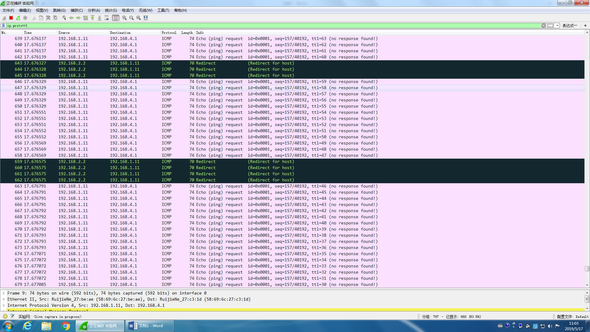
在路由器之间加入一台交换机 Switch1(不用配置),并连上一台主机(PC3),见下图。在 Switch1 上配置端口镜像(见上面「实验命令」),捕捉经过 F0/15 的 IP 分组,并送往 F0/5, PC3 可以用 WireShark 捕捉 ICMP 包(filter:ip.proto==1)。
用 PC1 ping 一个外部网络的无主 IP 地址会出现什么现象?截屏并分析结果
见下图,拆除 Router1 和 Router2 之间的以太网线,并用串行接口做实验,串行接口已经接好了,但不一定是下图标志的名称,要用#show interface(或#show ip interface brief 或#show ip interface s0/1)查看哪个串行接口已经接好(line is up,protocol is up)。配置 Router1 和 Router2 串行口的时钟、IP 地址和子网掩码,删除默认路由,配置静态路由(见上面命令或课件),令 PC1 可以 ping 通 PC2。
用 PC1 ping PC2 并截屏
此时由于 router1 的路由表里没有对应的目的地址,所以发往默认路由,即从 12.0168.2.1 发出,经过交换机,PC3 收到。而 router2 收到后,也是没有符合的目的地址,所以发往默认路由,经过交换机,到达 router1.重复上述操作,直至该帧的 TTL 减为 0,。在此过程中,PC3 一直收到。所以出现了上面的结果。
显示 Router1 的路由表并截屏
显示 Router2 的路由表并截屏

用#show running-config 显示 Router1 的当前配置,并粘贴在下面
1
2
3
4
5
6
7
8
9
10
11
12
13
14
15
16
17
18
19
20
21
22
23
24
25
26
27
28
29
30
31
32
33
34
35
36
37
38
39
40
41
42
43
44
45
46
47
48
49
50
51
52
53
54
55
56
57
58
59
60
61
62
63
64
65
66
67
68
69
70
71
72
73
74
75
76
77
78
79
80
81
82
83
84
85
86
87
88
89
90
91
92
93
94
95
96
97
98
99
100
101
102
103
104
105
106
107
108
109
110
111
112
113
114
115
116
117
118
119
120
121
122
123
124
125
126
127
128
129
130
131
132
133
134
135
136
137
138
139
140
141
142
143
144
145
146
147
148
149
150
151
152
153
154
155
156
157
158
159
160
161
162
163
164
165
166
167
168
169
170
171
172
173
174
175
176
177
178
179
180
181
182
Building configuration...
Current configuration : 1913 bytes

!
version RGOS 10.4(3b23) Release(176514)(Mon Jul 28 18:19:31 CST 2014 -ngcf62)
hostname 18-RSR20-1
webmaster level 0 username admin password 7 06073a0e261b
!
!
!
!
!
!
diffserv domain default
!
!
!
!
cwmp
!
!
!
!
!
!
vlan 1
!
!
no service password-encryption
!
!
!
!
!
!
!
!
!
!
!
!
!
!
!
!
!
!
!
control-plane
!
control-plane protocol
 no acpp
!
control-plane manage
 no port-filter
 no arp-car
 no acpp
!
control-plane data
 no glean-car
 no acpp
!
!
!
!
enable service web-server http
enable service web-server https
!
!
!
!
!
!
!
!
!
!
!
!
!
!
!
interface Serial 2/0
 encapsulation HDLC
 ip address 192.168.2.1 255.255.255.0
 bandwidth 512
!
interface FastEthernet 1/0
!
interface FastEthernet 1/1
!
interface FastEthernet 1/2
!
interface FastEthernet 1/3
!
interface FastEthernet 1/4
!
interface FastEthernet 1/5
!
interface FastEthernet 1/6
!
interface FastEthernet 1/7
!
interface FastEthernet 1/8
!
interface FastEthernet 1/9
!
interface FastEthernet 1/10
!
interface FastEthernet 1/11
!
interface FastEthernet 1/12
!
interface FastEthernet 1/13
!
interface FastEthernet 1/14
!
interface FastEthernet 1/15
!
interface FastEthernet 1/16
!
interface FastEthernet 1/17
!
interface FastEthernet 1/18
!
interface FastEthernet 1/19
!
interface FastEthernet 1/20
!
interface FastEthernet 1/21
!
interface FastEthernet 1/22
!
interface FastEthernet 1/23
!
interface GigabitEthernet 0/0
 ip address 192.168.1.1 255.255.255.0
 duplex auto
 speed auto
!
interface GigabitEthernet 0/1
 duplex auto
 speed auto
!
interface VLAN 1
!
!
!
!
!
!
!
!
!
!
!
!
!
!
!
!
!
!
!
!
ip route 192.168.3.0 255.255.255.0 192.168.2.2
!
!
!
!
!
ref parameter 75 140
line con 0
line aux 0
line tty 1
 modem InOut
line vty 0 4
 login
 password b402
!
!
end
用#show running-config 显示 Router2 的当前配置,并粘贴在下面
1
2
3
4
5
6
7
8
9
10
11
12
13
14
15
16
17
18
19
20
21
22
23
24
25
26
27
28
29
30
31
32
33
34
35
36
37
38
39
40
41
42
43
44
45
46
47
48
49
50
51
52
53
54
55
56
57
58
59
60
61
62
63
64
65
66
67
68
69
70
71
72
73
74
75
76
77
78
79
80
81
82
83
84
85
86
87
88
89
90
91
92
93
94
95
96
97
98
99
100
101
102
103
104
105
106
107
108
109
110
111
112
113
114
115
116
117
118
119
120
121
122
123
124
125
126
127
128
129
130
131
132
133
134
135
136
137
138
139
140
141
142
143
144
145
146
147
148
149
150
151
152
153
154
155
156
157
158
159
160
161
162
163
164
165
166
167
168
169
170
171
172
173
174
175
176
177
178
179
180
181
182
183
184
185
186
187
18-RSR20-2(config)#show running-config

Building configuration...
Current configuration : 1971 bytes

!
version RGOS 10.4(3b23) Release(176514)(Mon Jul 28 18:19:31 CST 2014 -ngcf62)
hostname 18-RSR20-2
webmaster level 0 username admin password 7 073f07221c1c
!
!
!
!
!
!
diffserv domain default
!
!
!
!
cwmp
!
!
!
!
!
!
vlan 1
!
!
no service password-encryption
!
!
!
!
!
!
!
!
!
!
!
!
!
!
!
!
!
!
!
control-plane
!
control-plane protocol
 no acpp
!
control-plane manage
 no port-filter
 no arp-car
 no acpp
!
control-plane data
 no glean-car
 no acpp
!
!
!
!
enable service web-server http
enable service web-server https
!
!
!
!
!
!
!
!
!
!
!
!
!
!
!
interface Serial 2/0
 encapsulation HDLC
 ip address 192.168.2.2 255.255.255.0
 clock rate 64000
 bandwidth 512
!
interface Serial 3/0
 encapsulation HDLC
 clock rate 64000
!
interface FastEthernet 1/0
!
interface FastEthernet 1/1
!
interface FastEthernet 1/2
!
interface FastEthernet 1/3
!
interface FastEthernet 1/4
!
interface FastEthernet 1/5
!
interface FastEthernet 1/6
!
interface FastEthernet 1/7
!
interface FastEthernet 1/8
!
interface FastEthernet 1/9
!
interface FastEthernet 1/10
!
interface FastEthernet 1/11
!
interface FastEthernet 1/12
!
interface FastEthernet 1/13
!
interface FastEthernet 1/14
!
interface FastEthernet 1/15
!
interface FastEthernet 1/16
!
interface FastEthernet 1/17
!
interface FastEthernet 1/18
!
interface FastEthernet 1/19
!
interface FastEthernet 1/20
!
interface FastEthernet 1/21
!
interface FastEthernet 1/22
!
interface FastEthernet 1/23
!
interface GigabitEthernet 0/0
 duplex auto
 speed auto
!
interface GigabitEthernet 0/1
 ip address 192.168.3.2 255.255.255.0
 duplex auto
 speed auto
!
interface VLAN 1
!
!
!
!
!
!
!
!
!
!
!
!
!
!
!
!
!
!
!
!
ip route 192.168.1.0 255.255.255.0 192.168.2.1
!
!
!
!
!
ref parameter 75 140
line con 0
line aux 0
line vty 0 4
 login
 password b402
!
!
end
实验体会
本次实验中,我们遇到了一些问题,有时配置是(我们认为)正确的但是总是 ping 不通,然后过了一段时间后结果又正常了,有些让人抓不到头脑。所幸最终是把实验做完了。在本次实验中我了解了静态路由的一些配置,对于一些情况也可以判断出问题所在。
Related posts