计数器的设计
post on 03 Jul 2018 about 3368words need 12min
CC BY 4.0 (除特别声明或转载文章外)
如果这篇博客帮助到你,可以请我喝一杯咖啡~
预习报告
内容一
使用 JK 触发器设计一个 16 进制异步减法计数器,并用逻辑分析仪观察并记录 CP 和每一位的输出波形。
JK 触发器功能/真值表
| CP 时钟 | J | K | 工作状态 | $Q^+$ |
|---|---|---|---|---|
| $\downarrow$ | 0 | 0 | 保持 | Q |
| $\downarrow$ | 0 | 1 | 置零 | 0 |
| $\downarrow$ | 1 | 0 | 置一 | 1 |
| $\downarrow$ | 1 | 1 | 翻转 | $\overline Q$ |
用 Proteus 设计电路,并运行仿真
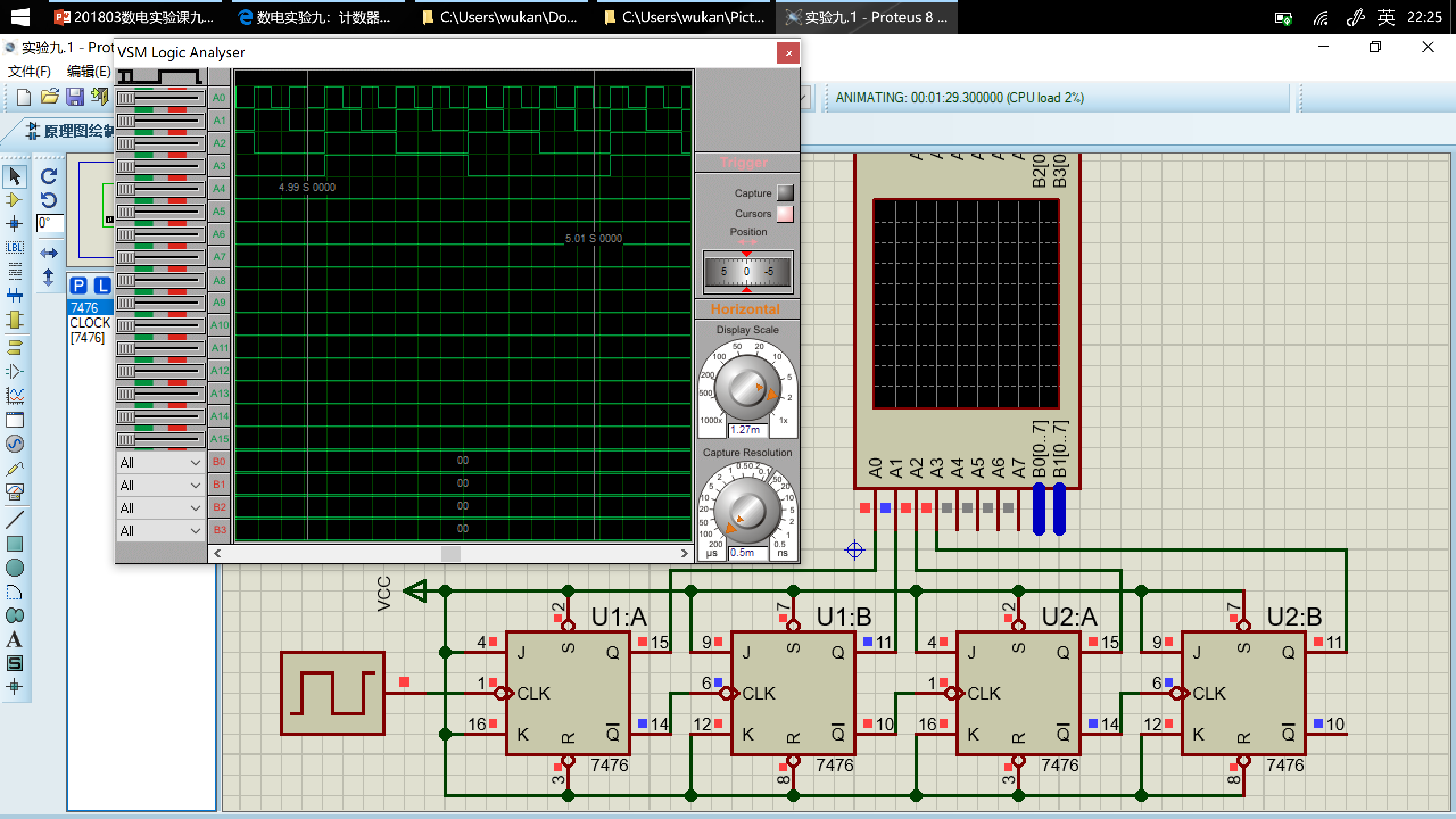
如图,$A_0\dots A_3$分别对应模拟的$Q_0\dots Q_3$端口。
可以看出,在一个周期内$Q_3Q_2Q_1Q_0$的变化顺序依次为
$0000\to1111\to1110\to1101\to1100\to1011\to1010\to1001\to1000\to0111\to0110\to0101\to0100\to0011\to0010\to0001\to0000\to\dots$
符合设计预期。
内容二
使用 JK 触发器设计一个 16 进制同步加法计数器,并用逻辑分析仪观察并记录 CP 和每一位的输出波形。
用 Proteus 设计电路,并运行仿真
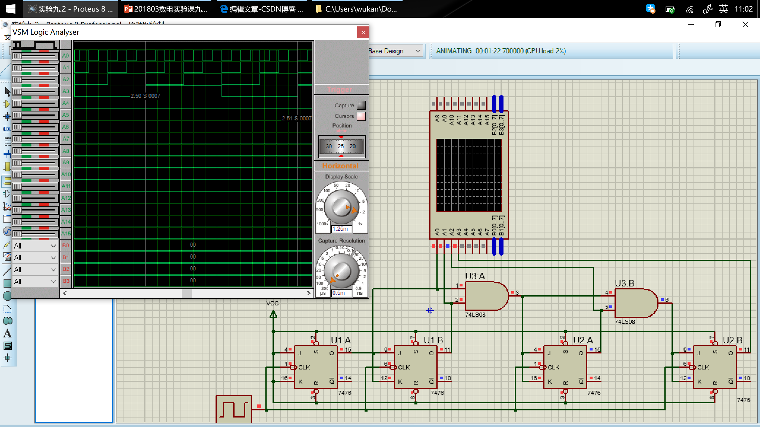
如图,$A_0\dots A_3$分别对应模拟的$Q_0\dots Q_3$ 端口。
可以看出,在一个周期内$Q_3Q_2Q_1Q_0$的变化顺序依次为
$0000\to0001\to0010\to0011\to0100\to0101\to0110\to0111\to1000\to1001\to1010\to1011\to1100\to1101\to1110\to1111\to0000\dots$
符合设计预期。
内容三
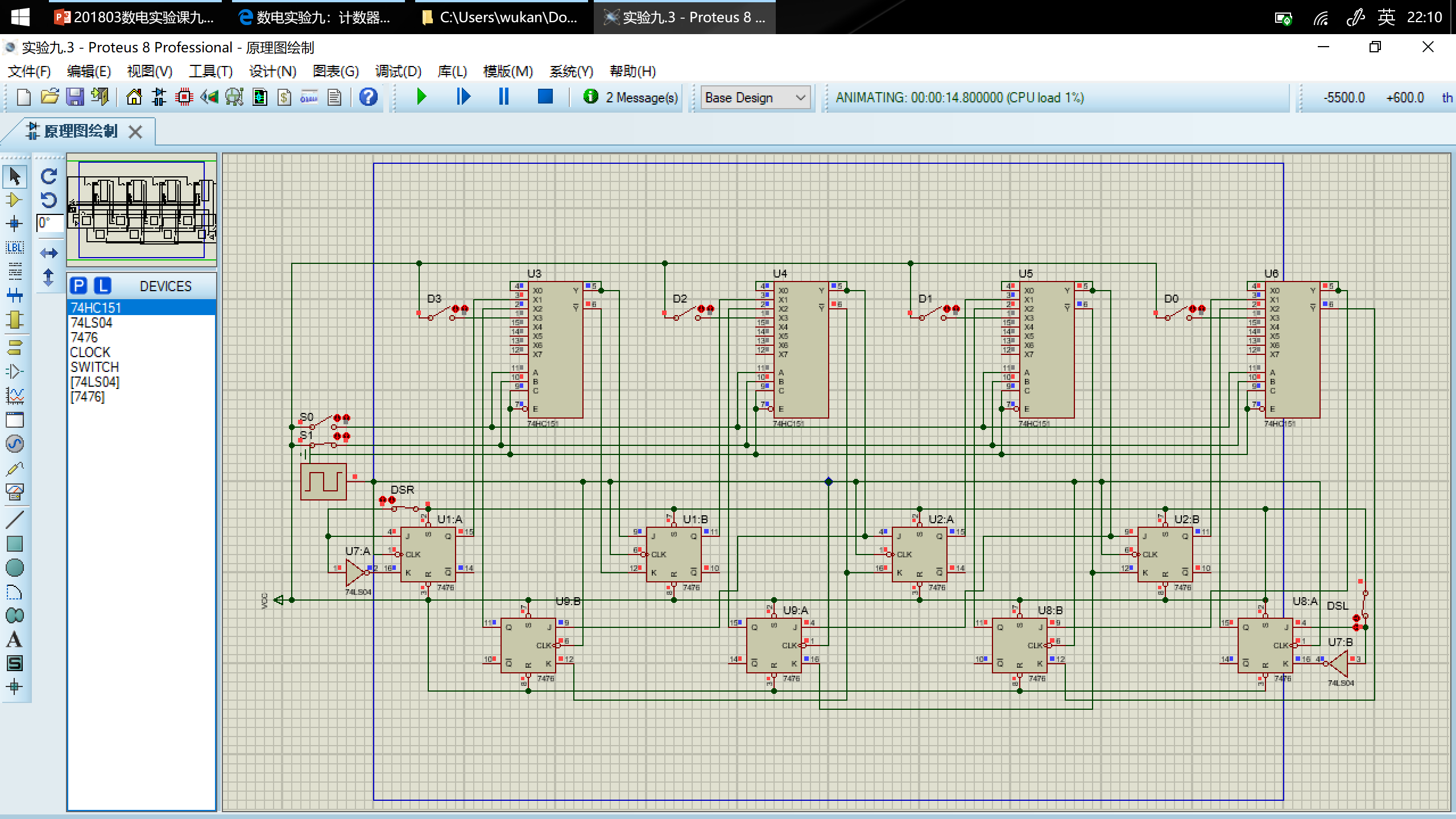
使用 JK 触发器和门电路设计实现一个二进制四位计数器模仿 74LS194 功能。要求在实验箱上设计实现左移或右移功能;在 proteus 软件上实现置零,保持,左移,右移,并行送数功能。
74LS194 功能/真值表
| CP 时钟 | $\overline{Cr}$清零 | ${S_1}$ | ${S_0}$ | 工作状态 | $Q_A^+$ | $Q_B^+$ | $Q_C^+$ | $Q_D^+$ |
|---|---|---|---|---|---|---|---|---|
| $\uparrow$ | 0 | X | X | 置零 | 0 | 0 | 0 | 0 |
| $\uparrow$ | 1 | 0 | 0 | 保持 | $Q_A$ | $Q_B$ | $Q_C$ | $Q_D$ |
| $\uparrow$ | 1 | 0 | 1 | 右移 | $D_{SR}$ | $Q_A$ | $Q_B$ | $Q_C$ |
| $\uparrow$ | 1 | 1 | 0 | 左移 | $Q_B$ | $Q_C$ | $Q_D$ | $D_{SL}$ |
| $\uparrow$ | 1 | 1 | 1 | 并行送数 | $D_0$ | $D_1$ | $D_2$ | $D_3$ |
用 Proteus 设计电路,并运行仿真
内容四
用 JK 触发器和门电路设计一个特殊的 12 进制同步计数器如下:
$0001\to0010\to0011\to0100\to0101\to0110\to0111\to1000\to1001\to1010\to1011\to1100\to0001\to\dots$
并用逻辑分析仪观察并记录 CP 和每一位的输出波形。
注意:这个 12 进制同步计数器没有 00 状态,要考虑自启动。
次态卡诺图
| $Q_3^+Q_2^+\setminus Q_1^+Q_0^+$ | 00 | 01 | 11 | 10 |
|---|---|---|---|---|
| 00 | xxxx | 0010 | 0100 | 0011 |
| 01 | 0101 | 0110 | 1000 | 0111 |
| 11 | 0001 | xxxx | xxxx | xxxx |
| 10 | 1001 | 1010 | 1100 | 1011 |
卡诺图化简得到每个触发器方程
| $Q_3^+Q_2^+\setminus Q_1^+Q_0^+$ | 00 | 01 | 11 | 10 |
|---|---|---|---|---|
| 00 | x | 0 | 0 | 0 |
| 01 | 0 | 0 | 1 |
0 |
| 11 | 0 | x | x | x |
| 10 | 1 |
1 |
1 |
1 |
$Q_3^+=Q_3\overline{Q_2}+\overline{Q_3}Q_2Q_1Q_0$
| $Q_3^+Q_2^+\setminus Q_1^+Q_0^+$ | 00 | 01 | 11 | 10 |
|---|---|---|---|---|
| 00 | x | 0 | 1 |
0 |
| 01 | 1 |
1 |
0 | 1 |
| 11 | 0 | x | x | x |
| 10 | 0 | 0 | 1 |
0 |
$Q_2^+=\overline{Q_3}Q_2\overline{Q_1}+\overline{Q_2}Q_1Q_0+\overline{Q_3}Q_2\overline{Q_0}$
| $Q_3^+Q_2^+\setminus Q_1^+Q_0^+$ | 00 | 01 | 11 | 10 |
|---|---|---|---|---|
| 00 | x | 1 |
0 | 1 |
| 01 | 0 | 1 |
0 | 1 |
| 11 | 0 | x |
x | x |
| 10 | 0 | 1 |
0 | 1 |
$Q_1^+=Q_1\overline{Q_0}+\overline{Q_1}Q_0$
| $Q_3^+Q_2^+\setminus Q_1^+Q_0^+$ | 00 | 01 | 11 | 10 |
|---|---|---|---|---|
| 00 | x |
0 | 0 | 1 |
| 01 | 1 |
0 | 0 | 1 |
| 11 | 1 |
x | x | x |
| 10 | 1 |
0 | 0 | 1 |
$Q_0^+=\overline{Q_0}$
驱动器方程
$J_3=Q_2Q_1Q_0,K_3=Q_2$
$J_2=Q_1Q_0,K_2=\overline{\overline{Q_3}(\overline{Q_1}+\overline{Q_0})}=Q_3+Q_1Q_0$
$J_1=K_1=Q_0$
$J_0=K_0=1$
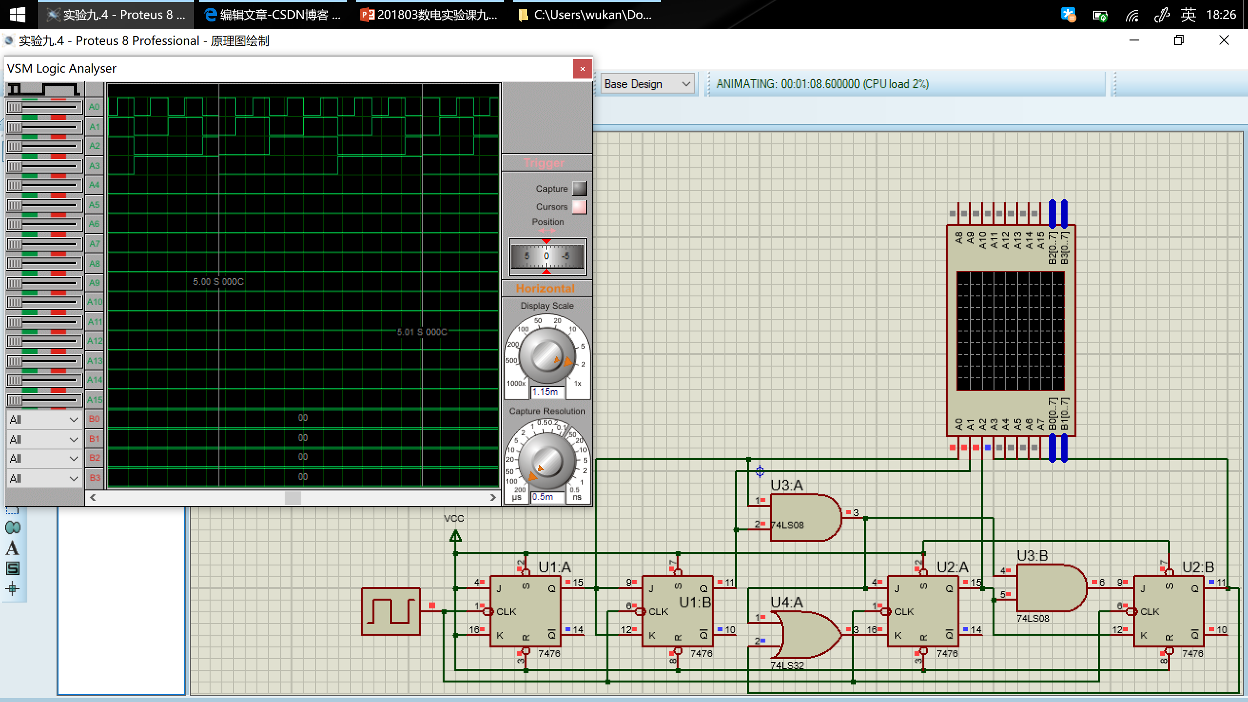
用 Proteus 设计电路,并运行仿真
在图中 $A_0\dots A_3$对应$Q_0\dots Q_3$。在波形的一个周期里,其变化符合设计预期。
内容五
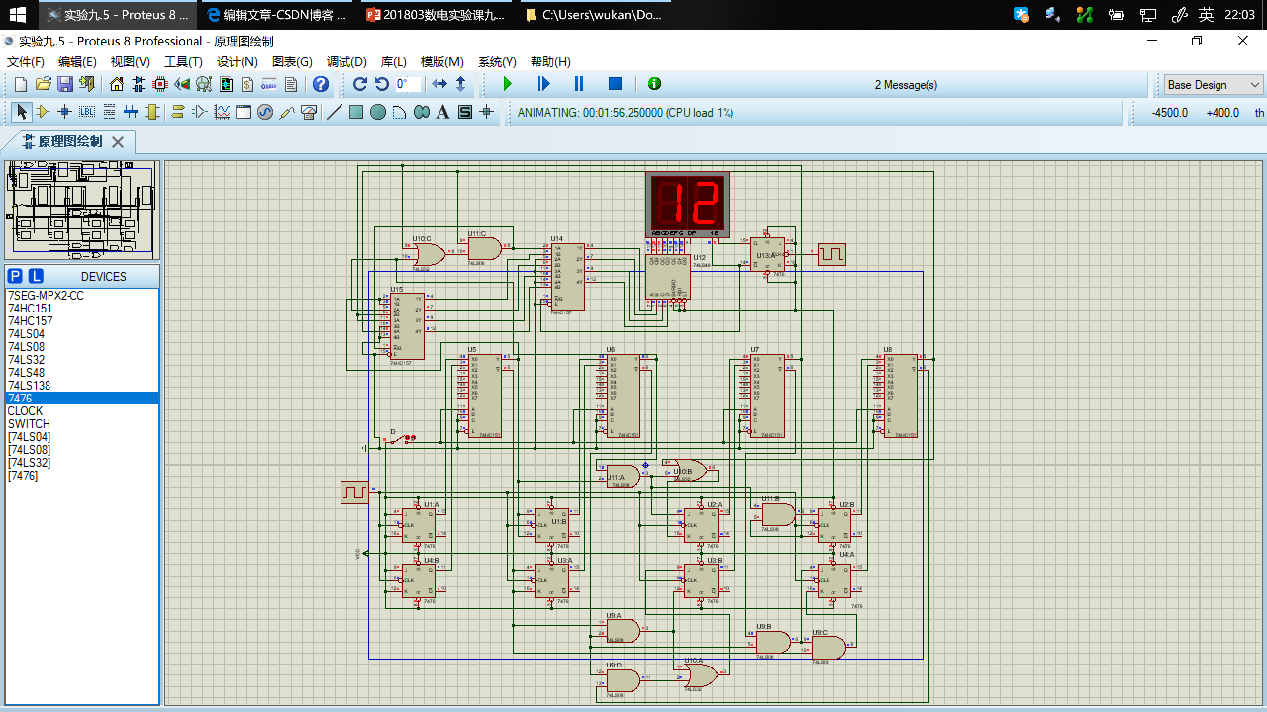
使用 Protues 和 Vivado 实现一个有控制变量 D 的 12 进制计数器(12 进制计数器状态转换图如内容四),并在 7 段数码管上显示计数结果。
由于 D=0 时(加)的驱动方程已在内容四得出,下面仅涉及 D=1(减)的状态。
次态卡诺图
| $Q_3^+Q_2^+\setminus Q_1^+Q_0^+$ | 00 | 01 | 11 | 10 |
|---|---|---|---|---|
| 00 | xxxx | 1100 | 0010 | 0001 |
| 01 | 0011 | 0100 | 0110 | 0101 |
| 11 | 1011 | xxxx | xxxx | xxxx |
| 10 | 0111 | 1000 | 1010 | 1001 |
卡诺图化简得到每个触发器方程
| $Q_3^+Q_2^+\setminus Q_1^+Q_0^+$ | 00 | 01 | 11 | 10 |
|---|---|---|---|---|
| 00 | x |
1 |
0 | 0 |
| 01 | 0 | 0 | 0 | 0 |
| 11 | 1 |
x |
x |
x |
| 10 | 0 | 1 |
1 |
1 |
$Q_3^+=Q_3Q_2+Q_3Q_1+Q_3Q_0+\overline{Q_3}\,\overline{Q_2}\,\overline{Q_1}$
| $Q_3^+Q_2^+\setminus Q_1^+Q_0^+$ | 00 | 01 | 11 | 10 |
|---|---|---|---|---|
| 00 | x |
1 |
0 | 0 |
| 01 | 0 | 1 |
1 |
1 |
| 11 | 0 | x |
x |
x |
| 10 | 1 |
0 | 0 | 0 |
$Q_2^+=\overline{Q_3}\,\overline{Q_2}\,\overline{Q_1}+\overline{Q_2}\,\overline{Q_1}\,\overline{Q_0}+Q_2Q_1+Q_2Q_0$
| $Q_3^+Q_2^+\setminus Q_1^+Q_0^+$ | 00 | 01 | 11 | 10 |
|---|---|---|---|---|
| 00 | x |
0 | 1 |
0 |
| 01 | 1 |
0 | 1 |
0 |
| 11 | 1 |
x | x |
x |
| 10 | 1 |
0 | 1 |
0 |
$Q_1^+=Q_1Q_0+\overline{Q_1}\,\overline{Q_0}$
| $Q_3^+Q_2^+\setminus Q_1^+Q_0^+$ | 00 | 01 | 11 | 10 |
|---|---|---|---|---|
| 00 | x |
0 | 0 | 1 |
| 01 | 1 |
0 | 0 | 1 |
| 11 | 1 |
x | x | x |
| 10 | 1 |
0 | 0 | 1 |
$Q_0^+=\overline{Q_0}$
驱动方程
$J_3=\overline{Q_2}\,\overline{Q_1},K_3=\overline{Q_2+Q_1+Q_0}=\overline{Q_2}\,\overline{Q_1}\,\overline{Q_0}$
$J_2=\overline{Q_1}\,\overline{Q_3}+\overline{Q_1}\,\overline{Q_0},K_2=\overline{Q_1+Q_0}=\overline{Q_1}\,\overline{Q_0}$
$J_1=K_1=\overline{Q_0}$
$J_0=K_0=1$
用 Proteus 设计电路,并运行仿真
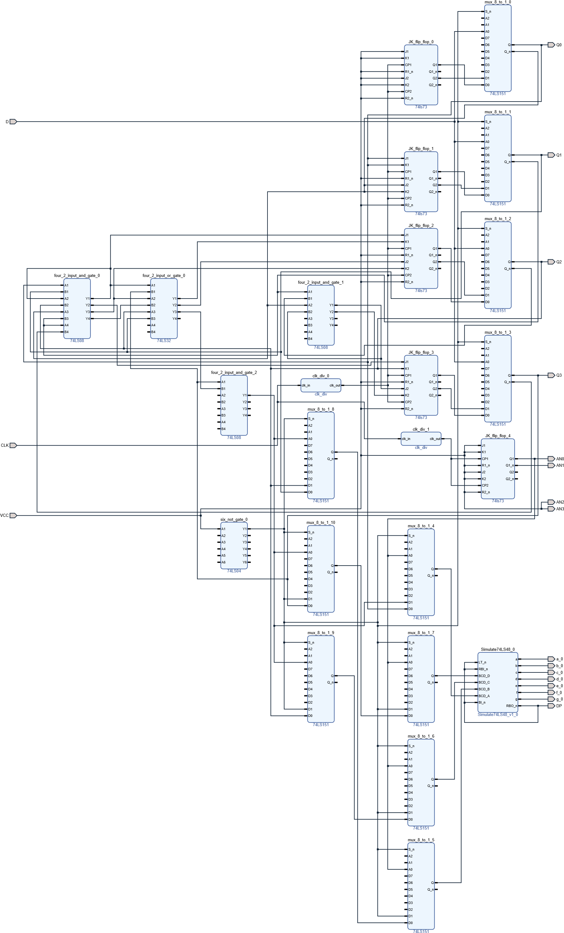
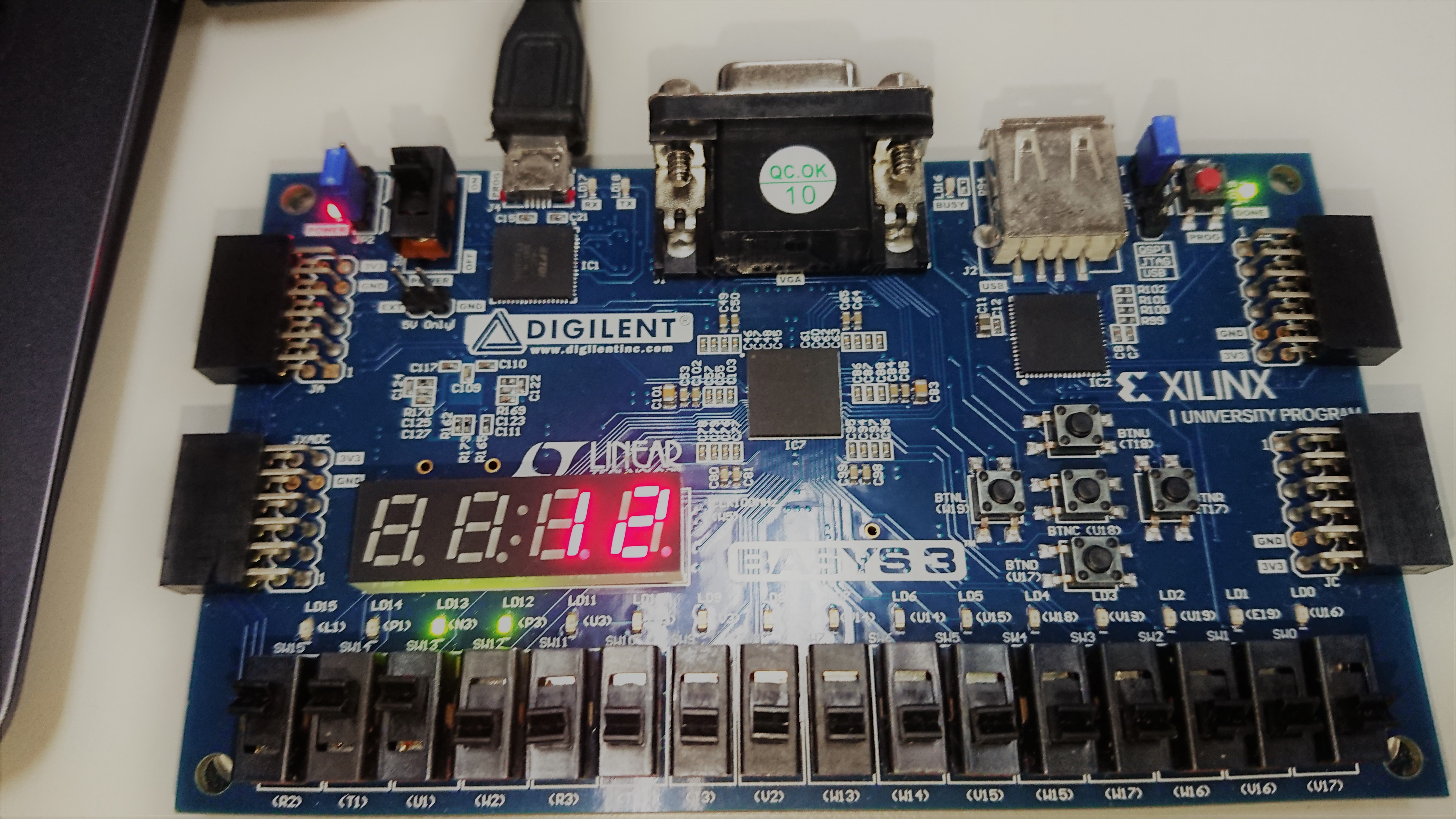
用 Vivado 设计电路,并烧写到 Basys3 实验板
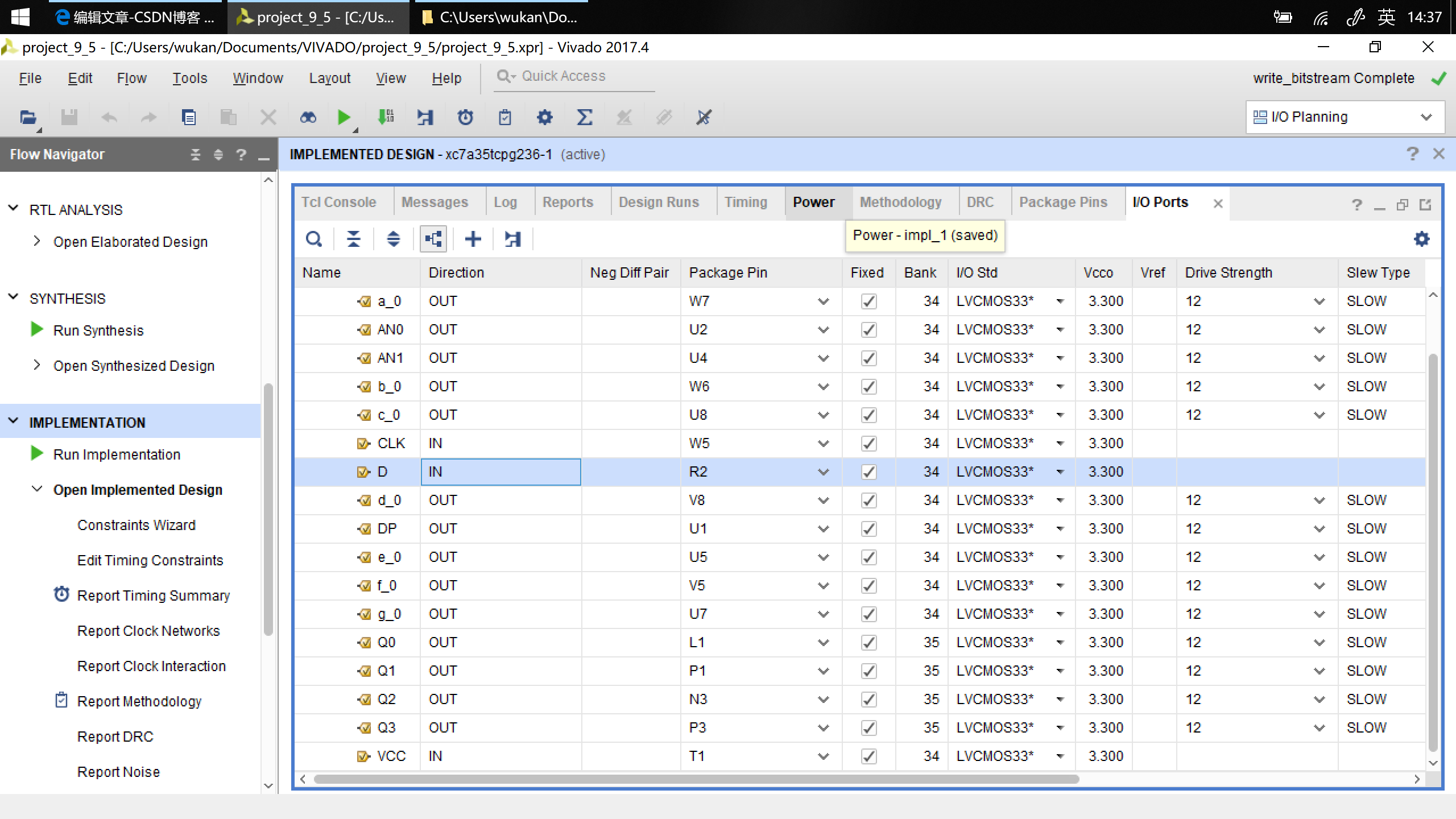
端口映射
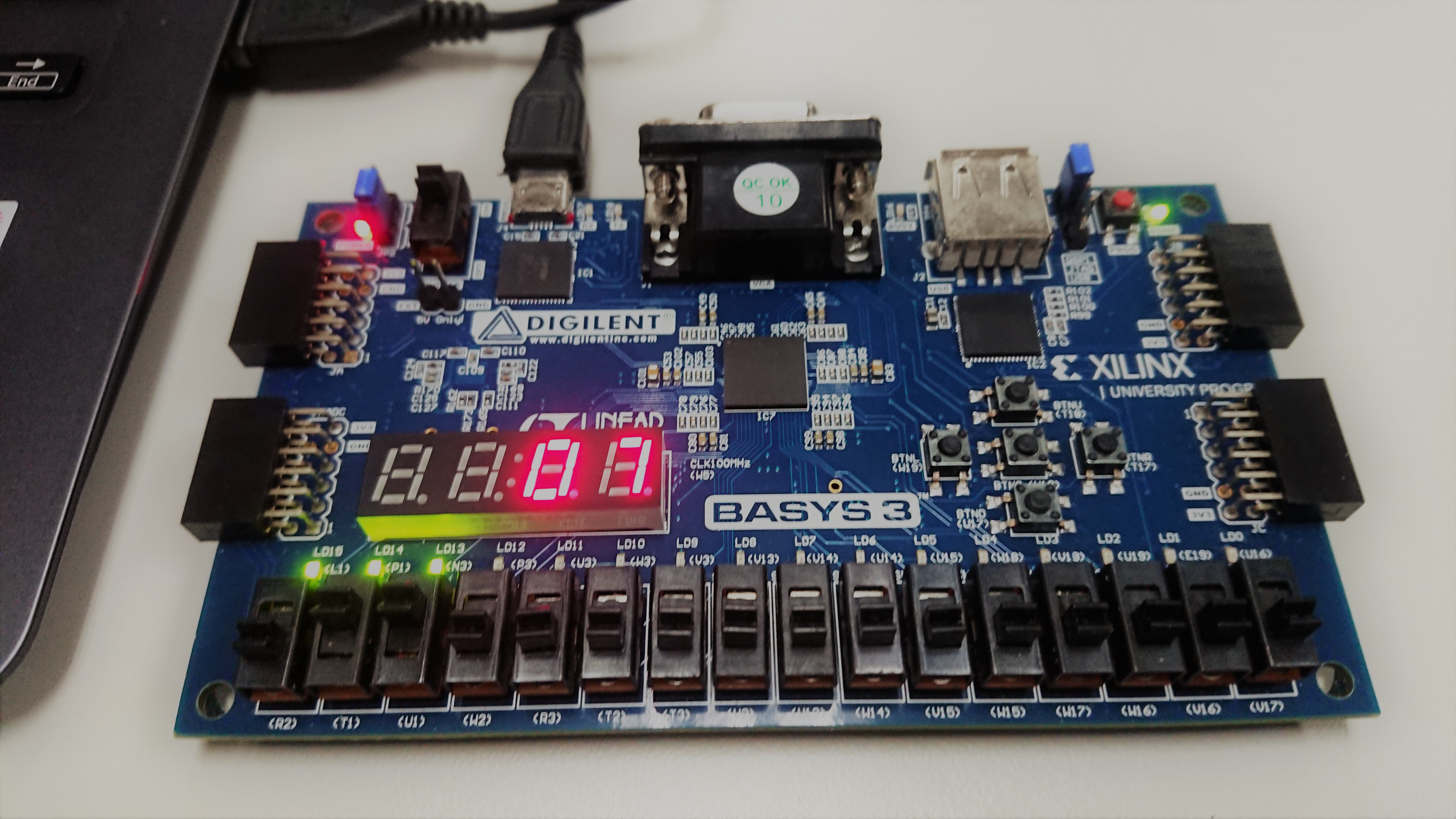
烧写到 Basys3 实验板
实验报告
内容四
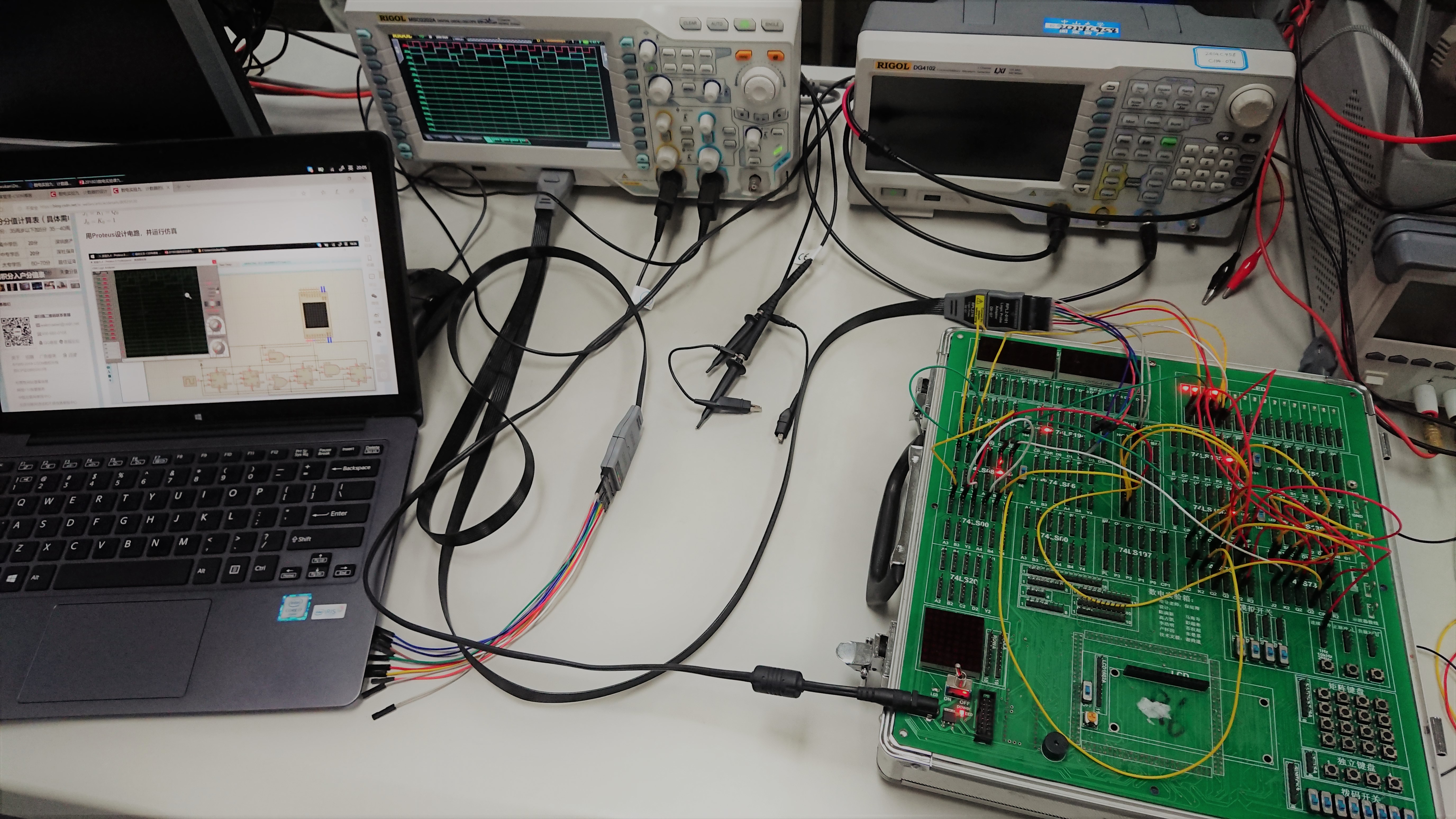
在实验箱上完成十二进制计数器,并在逻辑分析仪上得到其波形。
实验仪器及器件
数字电路实验箱、示波器;器件:74LS00*2,74LS08*2,74LS73*4、74LS197*1
代码转换电路设计
具体设计和仿真已在预习报告中完成。
转换电路的效果检验
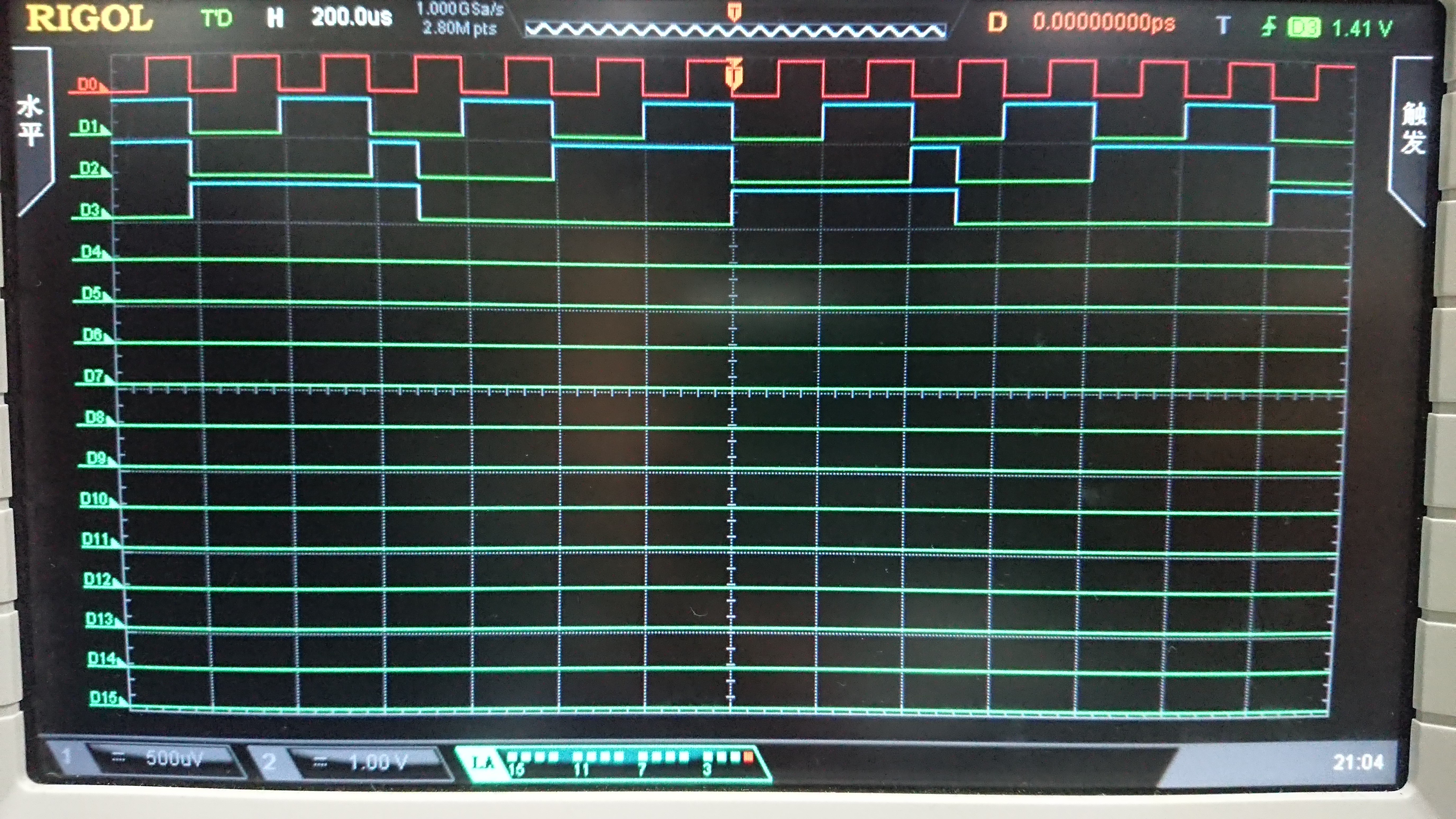
波形分析
连续脉冲频率为 2kHz,可以看出一个周期内 $D_0\dots D_3$ 恰构成二进制的 1~12,符合预期。
实验心得和体会
- 通过本次实验,我了解了 portuse 仿真软件上开关的使用。
- 通过本次实验,我熟悉了时序逻辑电路的分析步骤和方法。
- 通过本次实验,我更熟悉了示波器的使用。
- 通过本次实验,我提高了对错误电路的调试能力。
- 通过本次实验,我提高了电路的推导和检查能力。
Related posts
